
Wiring up an eBike Rear Light
Or: How I learned me some circuits and KiCad
Last year I bought a K6 Pro (K6F) Euybike. I rode nearly 2k miles the first year commuting around Los Angeles. I really wish the city would dispense with the cars and embrace bicycles. We’ve got really flat terrain, great weather all year round, and most trips are sub 5-mile (including my own!).

But this particular bicycle does not come with a tail light. Well, technically it does have a tiny little light below the seat powered by 2 button cell batteries. Which I easily forget turn it off. So I just stopped using it. However, I’ve got friends that worry about me, because Los Angeles lacks proper bicycle infrastructure AND has plenty of bad drivers that remain blind to the rare bicycle. They pushed me into getting a proper taillight.
But as I looked at my options, I realized I wanted a light that would also light up or blink when I hit the brakes. That means some kind of wiring into the bicycle’s battery.
Let’s embark on a 4 month journey of circuit design, CAD modeling, ordering the wrong parts, and various other mistakes!
Our First Obstacle: No wire for a tail light.
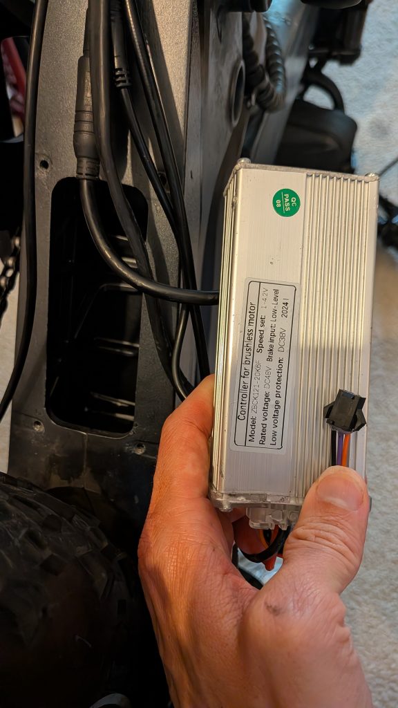
I know that the computer can detect the brakes, because it disengages the motor when I squeeze them. So I opened up the bike to have a look at the controller box only to find that it does not have a cable for the tail light. I did see some other weird unattached cable. I could not find any documentation or wiring diagram online, so I emailed Euybike. They confidently reported that weird connection is for a speed alarm that my bike does not use and there is no wire interface for a tail light.
So I had an evening where I sat down to scope out the cables. Most of these use some round water-safe connection, known as Julet. So I tediously, and carefully, use some really tiny clips meant for attaching to chips on a PCB to grab onto the pins of male plugs and sewing pins stuck in the sockets of female plugs to draw myself a reference sheet.
Our Second Obstacle: The ambiguous brake signal.
I discovered some weird things when I drew out the circuitry. The bike a has a consistently attached battery line of 48V — hence I took some care with those tiny clips and pins — but also it has a 4.5V line that shows high only when the bike computer is on. Strangely, this same line shows 0V when I squeeze the brake — it doesn’t matter which one.
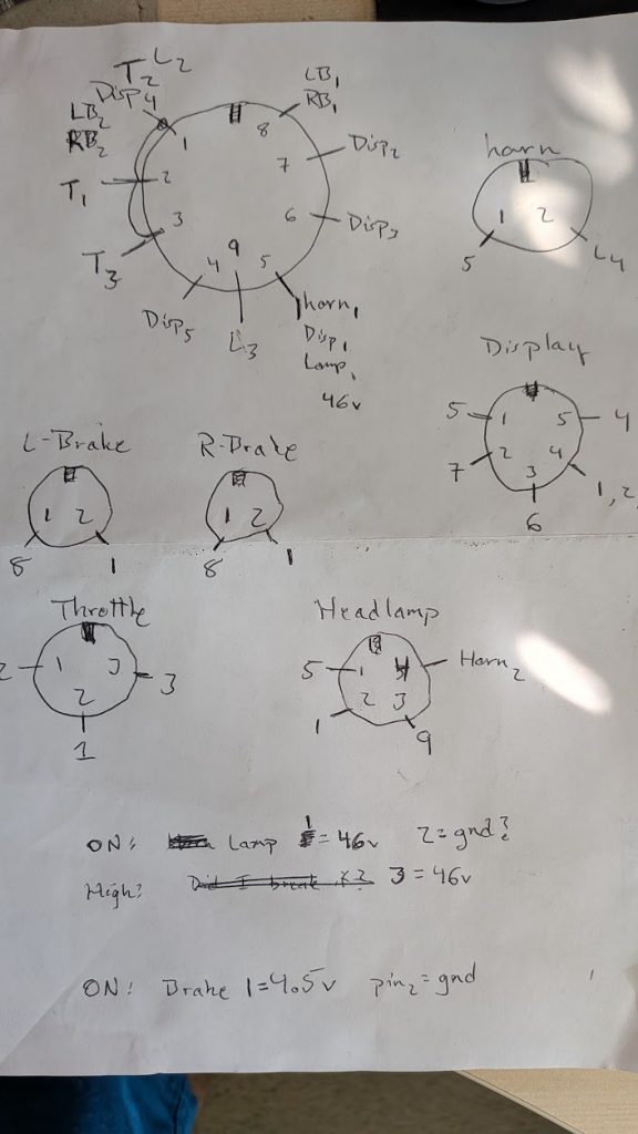
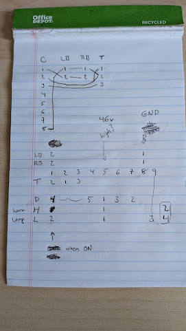
So if I want to use a tail light, I’ve got the one wire with 3 states:
| System off | 0V |
| System on | 4.5V |
| Brake Engaged | 0V |
I may not be an electronics engineer, but as software engineer, I can see that I’ve got 3 bits on this one wire, so I need some way of disambiguating. If my circuit-to-be sees 0V does that mean to light up and blink the brake light or does it mean to power off?
And then I suddenly remembered my Charlemagne: “I have but one messenger; who shall carry my meaning in the length of his absence.” I can let the circuit think the brake has engaged every time the line switches from 4.5V to 0V, but if it has seen 0V persist for more than a two minutes it can timeout and shutoff, because I would not realistically hold the brake engaged for that long.
Now I’ve got myself a plan!
Picking a Light
Initially, I thought I would pick up a simple tail light that turns on and off with the bike computer. I checked YouTube for some bike tailing reviews and comparisons. Which caused me to upgrade my plans to a light that includes flashing or increased brightness when I engaged the brake.
Last year, I had previously installed a light that used some kind of wireless transponder to control the light. But found the connection frustratingly unreliable. Also, I didn’t mount the light properly and it fell off somewhere. This time around, I’m gonna bolt the light on the bike, replacing the reflector.
I settled on this gizmo:
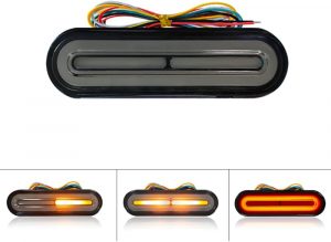
YouTube also had a few instructional videos on how to install such lights. But, recall, my bicycle does not have the correct connections. Which means, I need to make a circuit.
Designing The Circuit: A Conversation With Gemini
We haven’t hardly gotten started, but we’ve already picked up a handful of design constraints:
- The indicator for system on/of and brake engaged/not runs at 4.5V
- The battery, always available, runs at 48V
- The light runs on 12–80V
I can’t wire the light directly to the battery, because then it doesn’t turn on/off with the bike computer. I need some kind of micro-controller to watch that 4.5V line and toggle a switch that connects the light to the battery. Turns out these switches are known as MOSFETs. They’re a specialized form of transistor designed to handle a higher voltage and current load though one path.
Now a micro-controller can run off the 4.5V power line, except for the fact that it’ll turn off every time I engage the brake. So I need a much more reliable power source, like the battery. But that has much too high a voltage and needs to be stepped down. I quickly found out that I need a DC-DC buck converter to step down the battery voltage to a more manageable 4.5V. Many of these step down from 12V or 20V, so I had to take a bit of extra care and pick one that could handle 48V input.
OK, then I need these circuits:
- Detect the 4.5V has turned on and enable the tail light
- Detect the 4.5V has turned on and apply input power to the buck converter
- Detect the 4.5V has turned off and enable the brake light
- Detect the 4.5V has turned off for a solid minute and disable power to the buck converter
- Accept power input to the micro-controller from either the 4.5V line (bootup) or from the buck converter (continuous running).
Since I wrote code for a living, I don’t know very much about circuits. But I do think in terms of systems and I do have access to fancy AI chatbots like Gemini. I had a long conversations with the computer as it informed me that I needed something called a high-side or low-side switch. I cross-checked with YouTube videos put out by micro-controller hobbyists about building both of those and choosing between them. I asked Gemini plenty of questions every time something did not make sense. It can be a pretty good tutor.
Eventually I got first draft schematic for a light controller circuit!
                   IRF540N
+48V --- Light ---- Drain
                      |
     +------------ Source --- 100Ω --- pin ATtiny85
     |                |
GND -+--- 10kΩ ---- Gate
I mean it when I say “first draft”. Turns out this circuit needed lots of improvement, as I went on to learn later. As we iterated over several designs, I was observed some really interesting things about the chatbot!
- It has plenty of knowledge in this area, because power control circuits are very common.
- As long as we can describe the circuit connections it text, it can reason through the constraints, calculating voltage and current ranges.
- Based on the parts I have at hand (e.g. We designed with a 10kΩ, but I’ve only got 15kΩ) it can update the constraints.
- Once you have hard specifications (voltage and current ranges) the bot does a really good job at searching for parts that meet the constraints. For example, for a DC-DC buck converter going from 48V to 5V I need specifically a High Voltage version, LM2596HV.
- It cannot draw a circuit diagram worth beans, we have to keep it in text.
Our conversations would go something like:
Design me a circuit that does X
I see a connection between W and Z, can you explain?
What if the resistor is 15k instead of 10k, what needs to be adjusted?
How much current goes through the MOSFET when its on? What about when off?
Is that part really necessary? What are the alternatives?
More Circuit Design
I bought some parts based on that first design and started modeling the circuit in KiCad. That meant lots more YouTube videos on how to pick components and draw connection lines between them. I learned a very tiny bit about circuit simulation, enough to learn that I have ordered some wrong parts.
- The MOSFETs should be a ‘logical’ variant, so that they have an abrupt trigger between ‘on’ and ‘off’, and the threshold needs to be near 4.5V rather than 10V.
- I need P-type MOSFETs for high-side switching.
- The 2N2222 transistors are only rated for 40V, and my circuit sees higher than that.
So I made adjustments to the circuit, went over it with Gemini, double-checked all the currents and voltages, updated my parts list and ordered some new variants of the MOSFETs and transistors that fit the specifications. Eventually I was able to make a working physical prototype!
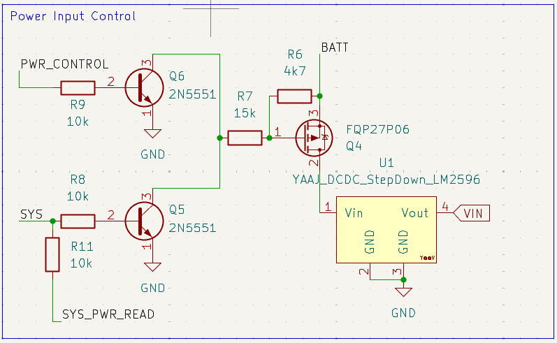
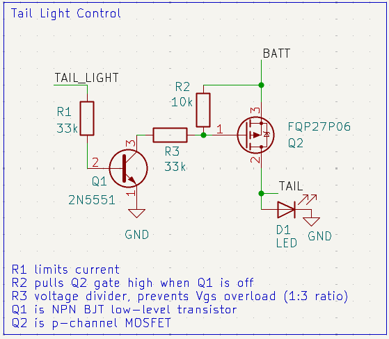
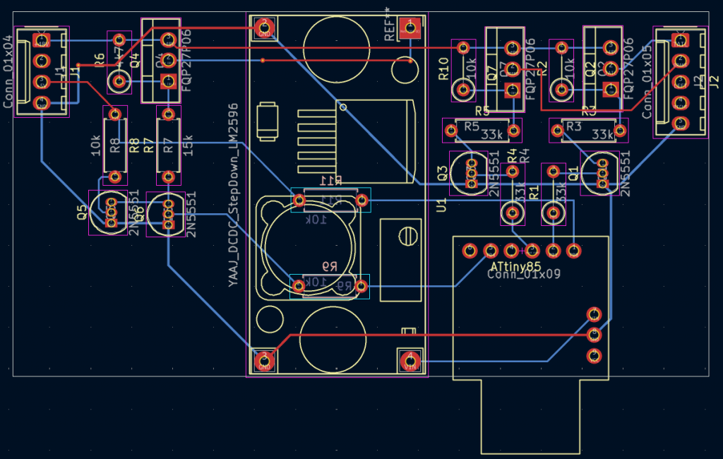
Even though I did not get a PCB printed, modeling it up turned out to be really helpful, because I could use a screenshot of it as a reference diagram when placing the components on the perfboard.
Cable Side-Quest
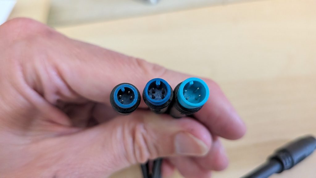
Meanwhile, I wanted to avoid splicing any of the cables on the bike and went searching for some Julet connections. The first challenge of this side-quest: How do I pull out a cable that has just the wires I need (GND, 4.5V brake, 48V battery)? I scraped through AliExpress and found this split-out cable, which didn’t have any documentation on what exactly it splits out! But it is the only option, so I ordered it and hoped for the best.
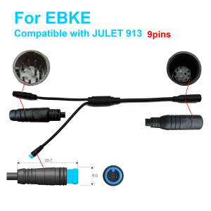
When it arrived (2 weeks later) I plugged it in and measured what came out. It split out exactly what I needed!
Next, I ordered some end cables so I would have some bits to solder into my circuit. The splitting cable also did not document the size of the connector, so I assumed it would be something common and got an M8 end (2 weeks wait on shipping). That was too big! So I tried for the next most common M6 (another 2 weeks wait on shipping). That was too small! Apparently it uses the rather rare and difficult to find M7 size (another 2 weeks wait on shipping). Perfect fit! In retrospect, I maybe should have messaged the seller to ask. Very annoying that they don’t have these kinds of important details on their listing!
Soldering the Circuit
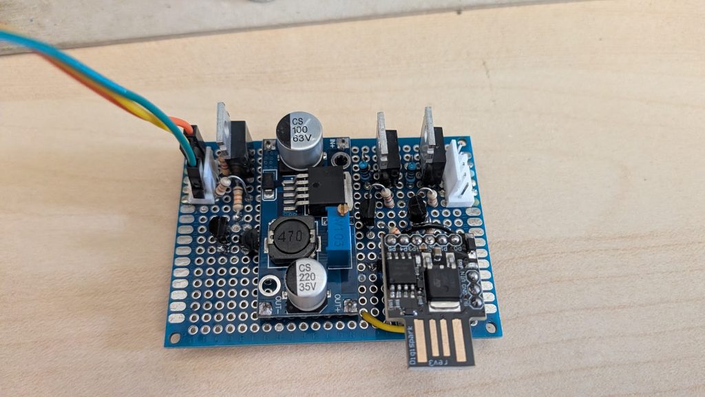
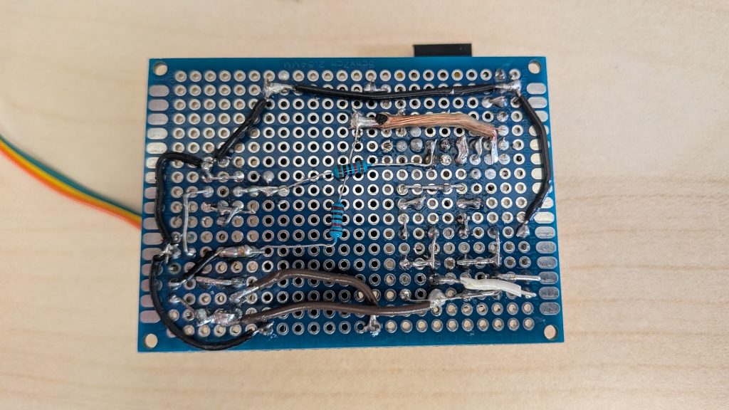
I spent several nights at the local makerspace — shout out to CrashSpace.org! — using their electronics bench to solder up and test my circuit on a perfboard. Given how much practice I need at soldering, and the fact that I made several mistakes, such as missing connections and soldering in the part backwards, I really should’ve just ordered one printed by JLPCB for $5.
Yeah, I could use some practice soldering 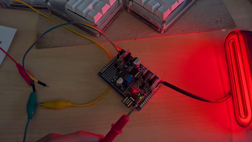
It took me an absurdly long time to get to this point!
Testing
I spent a considerable amount of time debugging my mistakes. I even burned out the data line on the ATtiny85 during my testing and had to order a new one. Gemini was also pretty helpful here, as I could explain a problem and it would compose a sequence of steps to validate the constructed circuit. For example, before plugging in a new ATtiny, I asked it how I could verify that I had enough protection in place and it came up with
Exercise 1: The “Resistance-to-Rail” Verification (Power Off)
Before plugging any microcontroller or power source in, you must verify that PB4 is electrically isolated from your main voltage rails.
Set your Multimeter to Continuity mode (or Resistance/Ohms mode).
Measure between the PB4 pad on your board (where Pin 5 of the ATtiny will go) and your High-Voltage Battery Rail (BATT or 16V/48V):
Expected Result: Open Loop (OL) or infinite resistance.
If it reads 0 ohms or low resistance: You have a solder bridge or a short circuit. Do not plug the chip in!
Measure between the PB4 pad and your Regulated 5V Rail (SYS or VCC):
Expected Result: Open Loop (OL) or infinite resistance.
Measure between the PB4 pad and the Gate of MOSFET Q4 (Power Input Control):
Expected Result: You should see a very high resistance (at least the sum of R9 + R7 + R6). If it is close to 0 ohms, the transistor Q6 is shorted or bypassed, meaning high voltage could leak straight back to PB4.
Exercise 2: The “Inline Current Limiting” Check (Power Off)
You want to physically confirm that the 10kΩ current-limiting resistor (R9) is actually sitting between the ATtiny’s PB4 pad and the transistor Q6 base.
Set your Multimeter to Resistance (Ohms) mode.
Place one probe on the physical PB4 pad (where the ATtiny pin will solder).
Place the other probe on the Base pin of transistor Q6.
Check the reading:
Expected Result: Exactly 10kΩ (or extremely close, matching your R9 resistor value).
If it reads 0 ohms: You have accidentally bypassed R9. This means when PB4 switches state, there is no resistor to limit the current, which will instantly kill the pin.
Exercise 3: Safe Simulated Bench Testing (Power On, No ATtiny)
You can test if your power-switching circuit actually works without risking the ATtiny85.
Keep the ATtiny85 removed from the circuit.
Power up the board (apply your 16V to the battery input).
Measure the voltage at the PB4 pad:
Expected Result: It should read 0V because nothing is driving it. The main circuit should remain completely powered down.
The “Soft Pull-Up” Test: Take a loose 10kΩ resistor (do not use a plain wire!).
Hold one end of the 10k resistor to your regulated 5V rail.
Touch the other end of the 10k resistor to the PB4 pad.
What should happen: This safely injects a weak 5V signal into PB4. Your power control circuit (Q6, Q5, Q4) should activate, turning on the main SYS power.
Verify Safety: While doing this, measure the current flowing through that temporary resistor if you can, or simply check that the voltage at the PB4 pad stays stable near 5V and doesn’t get pulled down to 0V.
Exercise 4: Code Safety Rule for PB4
When you write your firmware for the new ATtiny85, you must be extremely careful with how you configure PB4 in code.
On these dev boards, PB4 is shared with the USB data line, which means it undergoes electrical handshakes when plugged into a PC. To prevent the chip from fighting the USB host:
Always declare the pin mode explicitly: Make sure your code clearly defines pinMode(4, OUTPUT); before attempting any digitalWrite(4, LOW); commands.
Avoid rapid toggling at boot: Do not rapidly toggle PB4 HIGH and LOW in your setup() function. Give the chip a second to finish its USB handshake bootloader routine before your code takes absolute control of the pin.
Its ability to help me diagnose problems and explain what’s going on has been a really helpful feature!
Integration Trouble
For quite a few iterations, it would work great on the bench (where I tested it with 30v) and then fail to behave as expected. Not only did it spark when I plugged it in, it also turned on without waiting for me to turn the bike on! Which means that it would not be able to turn itself off. I tried a handful of different strategies. Can I lower the input voltage? Not really, it would generate too much heat to throw a resistor in to absorb that. Can I use the enable/disable pin on the LM2596HV buck converter? Re-design the circuit to test that, desolder the power input half of my board, re-solder it with a new configuration to pull the pin low (enable) and clamp high (disable) by default. Looks promising on the test bench, but then has the same failure mode. So, after a few iterations, I pull out the buck converter and see that >40v it has a breakdown and sends power to the output.
So I get on AliExpress and find a buck converter rated for 100v. Desolder the components yet again — I’m getting some practice with this step! Another NotebookLM session to re-design the circuit again for the new converter (it enables on high).
Because this new buck converter doesn’t have much documentation, and since the manufacturer may have cut some corners given the price, and it pegs an output at 5v so I won’t be using the Tiny’s onboard power regulator but connecting it direct, I also tested the converter by itself with the oscilloscope to see that it does not produce very much wobble on the output. So this time, the fourth castle I built, stayed up. I built it strong! I tested it on the bench, with full power, and it did not breakdown.
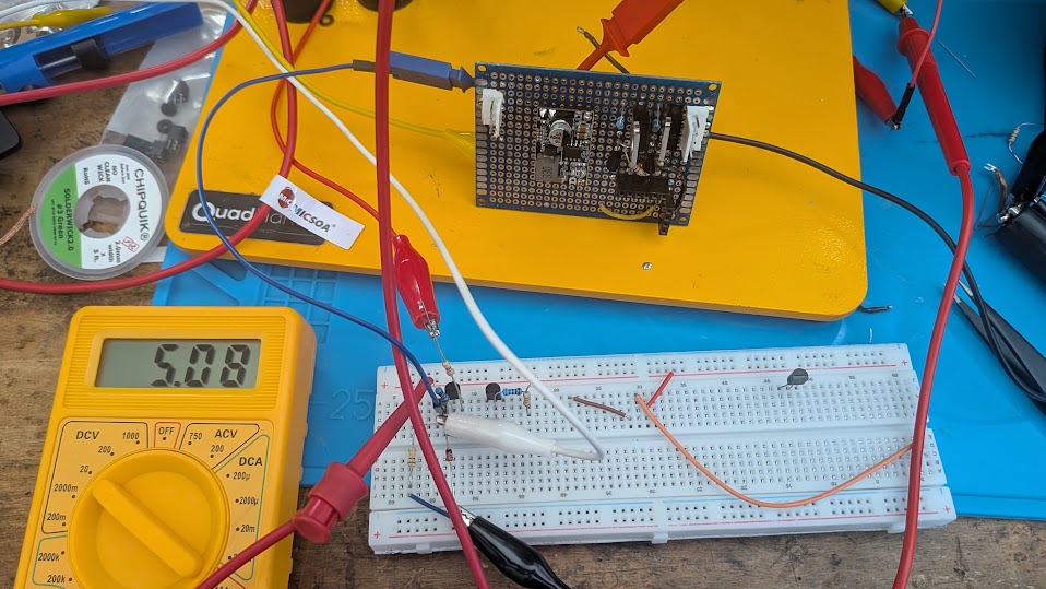
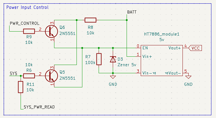
Ultimately, I went through 3 different converters before I was able to get one that worked. The LM2596HV didn’t do a good job of handling the 53v (at full charge) produced by the eBike and I burnt it out. A second attempt with an HT7886 didn’t work, because it doesn’t perform according to the specification — as input voltage increases, the output decreased. According to Gemini, it has something to do with a drift of the phase in the feedback loop. Adding an electrolytic capacitor across the output did not help. Finally, I had success with a TPS54560! which performed according to specification!
More than anything else, I learned that testing each module BEFORE integration can help to narrow down problems. And, as much as possible, incrementally add to the integration. For example, test the reliability and logic of the power circuit before adding the microcontroller, just to be sure you won’t overvoltage it.
Printing an Enclosure
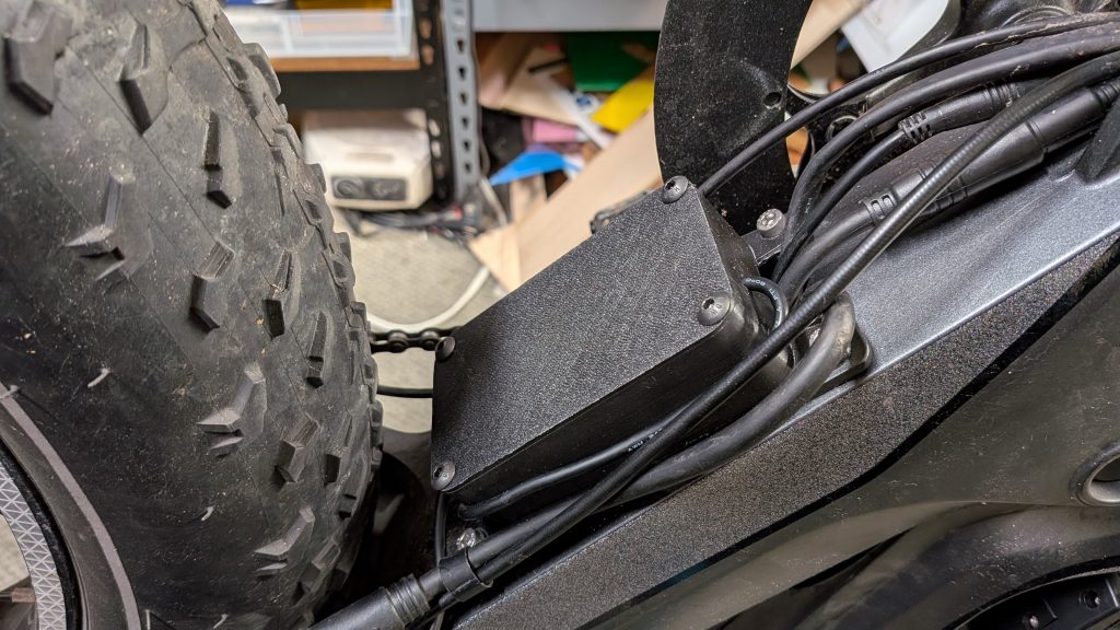
Initially I thought I could have a small circuit that would fit into the bike frame, in this pocket alongside the controller and its cables. But I found out, after soldering it together, that its just too big to go in there. So I had to figure out where to mount it. After considering a few different options — can it bolt on the frame? no. Is there room under the rear basket? yes, but what about the extra cabling? — I settled on mounting it with the controller.
In two separate phases, I modeled a box with lid in FreeCAD. I carefully considered how the cables might run in and out. Thinking a bit about water intrusion and then deciding I’m not gonna worry about that very much. I made sure that neither the box nor the lid would have features needing support when I 3d print them. And I avoided clips because they are huge effort for me to model.
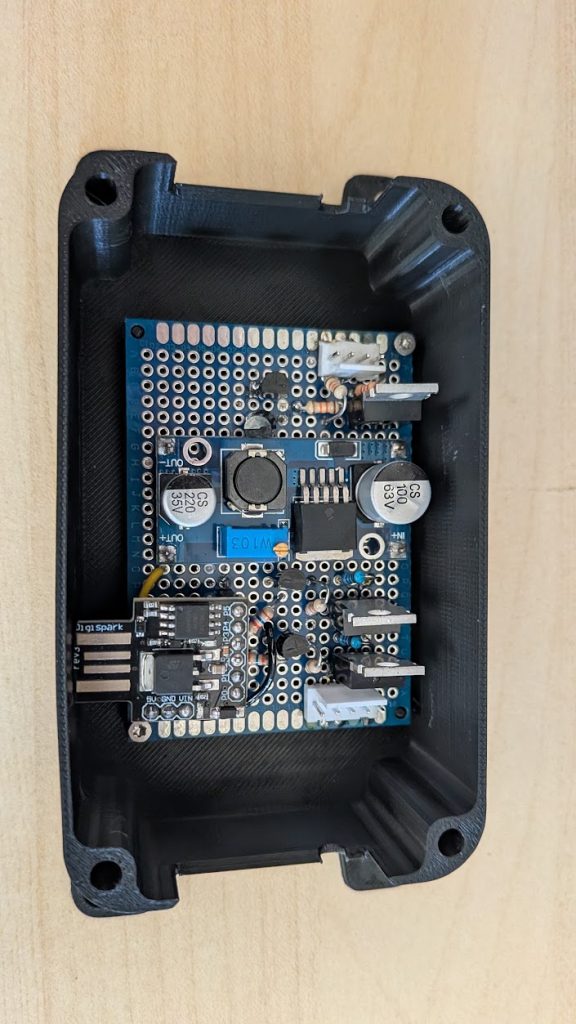
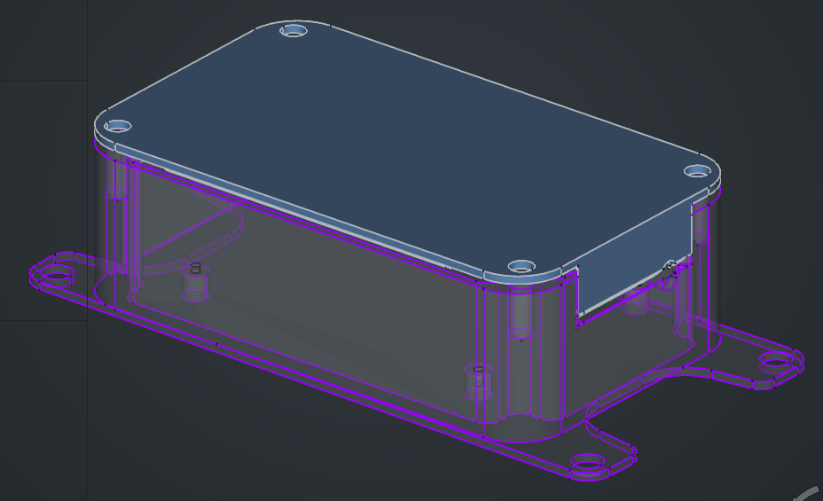
Then I figured out where I’m gonna mount it and added modeling for an attachment plate, measuring the bicycle to get a good fit. Again, there are plenty of details to learn here. Like the good sequence of operations to take when designing the model (do the fillets last). I got myself in a bind a handful of times when I tried to re-order the operations. I even broke some reference somewhere and had to start from scratch. I learned about how to use, varsets, external geometry, and subshape binders to keep things adjustable. After I printed the first one, I discovered I had to adjust some things: length, width, height, offsets for the circuit standoffs, etc, so that things would actually fit inside it.
Coding the Logic
Because I didn’t need very many control wires I chose to design for an ATtiny85. In retrospect that was not a great idea. I really should have chose an esp32, because I didn’t think ahead that I might want to extend what the circuit can do. For example, with eps32 bluetooth I could have a connection with my phone, which opens up an app to control the light so I could have added in wiring for the right and left blinker. Sadly, those will remain unused.
Gemini is pretty familiar with the Arduino coding platform and was able to one-shot some code for controlling the power input, tail light, and brake light, and power off timer.
I have a tiny85 that I want to control a brake light.
- pin A control the tail light and should be always on
- pin C watches a 4.5v line go LOW that signals the brake has been engaged
- pin B controls the brake light and turns on when pin C detects LOW
- pin B controls the brake light and turns off when pin C detects HIGH
- when the brake is engaged a 1 minute timer start
- if the brake has been engaged for a full minute, pin D goes HIGH to turn the circuit off
// --- Pin Definitions ---
const int tailLightPin  = 0; // Pin A (PB0)
const int brakeLightPin = 1; // Pin B (PB1)
const int brakeSigPin   = 2; // Pin C (PB2)
const int shutoffPin    = 3; // Pin D (PB3)

// --- Timer and State Variables ---
unsigned long brakeStartTime = 0;
bool isBraking = false;
bool circuitShutOff = false;

// 1 minute = 60,000 milliseconds
const unsigned long TIMEOUT_MS = 60000;

void setup() {
  // Configure pins
  pinMode(tailLightPin, OUTPUT);
  pinMode(brakeLightPin, OUTPUT);
  pinMode(brakeSigPin, INPUT);
  pinMode(shutoffPin, OUTPUT);

  // Set initial states
  digitalWrite(tailLightPin, HIGH);  // Pin A: Tail light always ON
  digitalWrite(brakeLightPin, LOW);  // Pin B: Brake light initially OFF
  digitalWrite(shutoffPin, LOW);     // Pin D: Shutoff signal initially LOW
}

void loop() {
  // If the 1-minute timeout has triggered, halt all further logic
  if (circuitShutOff) {
    return;
  }

  // Read the 4.5v brake line
  int brakeSignal = digitalRead(brakeSigPin);

  // --- Logic for Brake Engaged (LOW) ---
  if (brakeSignal == LOW) {
    digitalWrite(brakeLightPin, HIGH); // Turn brake light ON

    if (!isBraking) {
      // The brake was just pressed. Start the timer.
      isBraking = true;
      brakeStartTime = millis();
    } else {
      // The brake is being held. Check how long it has been held.
      if (millis() - brakeStartTime >= TIMEOUT_MS) {
        // A full minute has passed
        digitalWrite(shutoffPin, HIGH); // Trigger circuit shutdown
        circuitShutOff = true;          // Lock the state
      }
    }
  }

  // --- Logic for Brake Disengaged (HIGH) ---
  else {
    digitalWrite(brakeLightPin, LOW);   // Turn brake light OFF
    isBraking = false;                  // Reset the braking state/timer
  }
}
But seriously, this code sucks! It’s got lots of conditions and state to worry about. I challenge you to think up a better approach before you mouse-over to see what I wrote as a replacement. (Highlight to reveal code).
// --- Pin Definitions ---
const int tailLightPin  = 0; // Pin A (PB0)
const int brakeLightPin = 1; // Pin B (PB1)
const int brakeSigPin   = 2; // Pin C (PB2)
const int shutoffPin    = 3; // Pin D (PB3)

// Timing
const unsigned long POLL_INTERVAL_MS = 20; // 50Hz
const unsigned long BRAKE_TIMEOUT_MS = 60000UL; // 1 minute
unsigned long shutDownTime = 0;

void setup() {
 shutDownTime = millis() + BRAKE_TIMEOUT_MS;

 pinMode(PIN_TAIL_LIGHT,  OUTPUT);
 pinMode(PIN_BRAKE_LIGHT, OUTPUT);
 pinMode(PIN_BRAKE_SENSE, INPUT);
 pinMode(PIN_POWER,       OUTPUT);

 // Set initial lights and toggle power state
 digitalWrite(PIN_TAIL_LIGHT, HIGH);
 digitalWrite(PIN_BRAKE_LIGHT, LOW);
 digitalWrite(PIN_POWER, HIGH);
}


void loop() {
  bool braking = (digitalRead(PIN_BRAKE_SENSE) == LOW);

  // update the brake light
  digitalWrite(PIN_BRAKE_LIGHT, braking);

  // system has been shut off (or break engaged for too long)
  if (braking && millis() > shutDownTime) {
    digitalWrite(PIN_POWER, LOW);
  }

  // brake released, delay the system shutoff
  if (!braking) {
    shutDownTime = millis() + BRAKE_TIMEOUT_MS;
  }

  delay(POLL_INTERVAL_MS);
}
The tooling to get this code onto the ATtiny85 was a bit frustrating. Snap packages wanted 32-bit libs, and my system is 64-bit. The deb package would not install, and I couldn’t figure out why. THe official Digistump board package worked, but ships with a version of micronucleus (the USB bootloader tool) so old it could not locate the device. etc. etc. Eventually, I found a combination of things that worked: used an unofficial (but highly recommended) github repo for digistump arduino that has an updated micronucleus and libusb.
And one weird quirk of the ATtiny: If PB5 (the RESET) pin has anything on it — even a pull-up resistor — it’ll hold the chip in reset forever. So I shuffled and re-mapped my control pins a few times as I ran into these issues.
Really Impressed by Electronics Engineering
One thing that really struck me during this project: every single component I bought has a datasheet describing its behavior under many conceivable condition. For example, the MOSFETs have a dozen graphs showing behavior under various voltages, currents, temperatures, etc. Many of the critical quantities have min and max values in a reference table. As an engineer, I know how time consuming it takes to gather such detail. They also need a testing harness with specialized equipment to record the data. They likely test several copies of the same part to mitigate and measure variance in production. I am very impressed that the industry puts this much effort into components that sell at such low price points. This monumental effort sits behind every device you’ve ever used. I used maybe 5 numbers out of that sheet (max rated current and voltage) for my application, but all of them are important for real electronics engineers doing more intricate work. The stuff I build (software) has far less measurement (and also less reliability — the effort is a cost trade-off).
I also really enjoyed using Notebook LM (now called Gemini Notebook) as a way to keep my ideas together. For example, though Gemini can’t draw a circuit, it was capable of reading a screenshot of one. Keeping descriptions to text proved the winning strategy. Fortunately, my circuits did not have very many wires or component, so I was able to describe them fully with text.
I made mistakes at every step. I bought the wrong parts based on a first draft. I soldered parts backwards and had to re-orient them. I burned out my microcontroller during testing. I didn’t do accurate measurements on my box and had to print it twice. I had a buck converter that couldn’t handle my input voltage. Those delays stacked up to extend the schedule to about 4 months! But I did learn a TON along the way.
I’ve never used KiCad before. I sampled how small details can affect the end product, and ended up swapping out components when I double-checked for voltage and current ratings. Some features I thought I could use (like an enable/disable pin on the first buck converter) but it turned out I could not (because it’s active in the wrong direction) but then ended up with a different part entirely and did use its enable/disable feature. I also discovered that prototyping on a breadboard has some value for finding errors that would have skipped all that desoldering time. And I learned some behavior patterns interacting with Gemini for something other than writing code (my core expertise).
Pictures in the post are outdated, because of many design iterations. You can download the final results at https://github.com/EricHennigan/3d-prints/tree/main/2026_bike_rear_light